Digital Effects Pedal
I’d wanted to build a guitar pedal for a while - mainly just to mess around with digital effects. This project was a good excuse to get familiar with audio codecs and hopefully end up with something that I could actually play/experiment with.
Design
I kept the analog stages pretty basic so I could focus on the digital stuff. The sound quality turned out OK despite minimal effort put into proper filtering etc. The pedal is based around a PIC32 microcontroller and I chose the AK4556 audio codec for the interface. Below is the circuit I came up with for the effects pedal:
The pedal’s input starts with the foot switch. I chose a 3PDT switch so that I could force the input to short to the output, bypassing the electronics altogether whilst simultaneously toggling an indicator LED. The signal first passes through an input buffer before entering the codec. Once the codec has measured the signal the MCU reads in the data over I2S using it’s SPI peripheral and then does the effects processing. The data is once again read out over I2S from the MCU to the codec which spits out the altered signal via it’s DAC. Before the signal exits the pedal it passes through an output stage consisting of a tone control and output buffer. The tone control is set up as an adjustable low-pass filter for cutting/boosting high frequencies. This website was a great resource for understanding effects pedal circuitry.
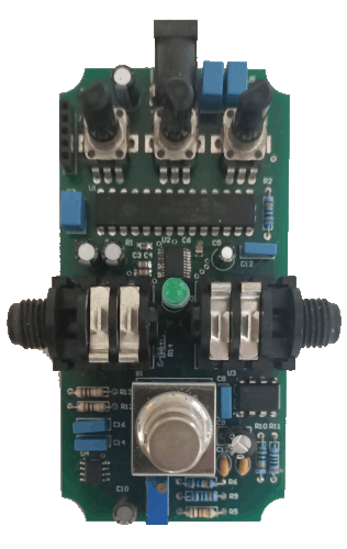
After finalising the circuit, I put together a PCB in Circuit Maker. Below shows various layers of the pcb as well as the final prototype. I’ve included a full parts list for the project here. I think all up the project cost around $70 AUD not including shipping.

With the prototype assembled I started writing the firwmare. Configuring the PIC to talk to the audio codec was slightly tedious but once that was working, I started by experimenting with some simple effects like distortion (just clipping the signal). This seemed to worked so I moved onto implementing a delay effect. Below I’ve included the main interrupt routine that takes data read in from the codec, then applies the delay effect.
void __ISR(_SPI1_VECTOR, IPL3AUTO)__SPI1Interrupt(void)

    // Recieve interrupt fired.
    if (IFS1bits.SPI1RXIF)
    {
        // Make sure we're only dealing with the right channel (the codec is a stereo device).
        if (channel)
        {
            right_channel = SPI1BUF;               // Pull data out of SPI buffer
            data = DELAY_Echo(right_channel);      // Apply effect
        }
        else
        {
            int dummy_left_channel = SPI1BUF;
        }

        // Set the channel back to right
        channel ^= 1;
    }

    // Transmit interrupt fired.
    if (IFS1bits.SPI1TXIF)
    {
        SPI1BUF = data;
    }

    // Error interrupt fired.
    if (IFS1bits.SPI1EIF) {}

    IFS1bits.SPI1RXIF = 0;
    IFS1bits.SPI1TXIF = 0;
    IFS1bits.SPI1EIF = 0;
}
The complete code is available on Github. Since the micro’s onboard memory was limited I had issues trying to extend the delay time (the more signal you want to record and delay the more memory you need). If I were to make another digital pedal I’d definitely include some external memory. This would make effects like reverb possible also.
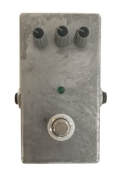
After I was happy with the firmware, I bought an enclosure and fit it to the PCB and called it complete :)


A Quick Demo…
Parts List
| Comment | Designator | Part Number | Quantity | Supplier | Supplier Code |
|---|---|---|---|---|---|
| 3PDT stomp switch | B1 | N/A | 1 | Jaycar | SP0766 |
| 10uF | C1, C2, C9, C15 | 50YXF10M5X11 | 4 | RS | 224-4325 |
| 0.1uF | C3, C4, C6 | CL21F104ZBCNNNC | 3 | Digikey | 1276-1007-1-ND |
| 2.2uF | C5 | EEA-GA1H2R2H | 1 | Digikey | P15835CT-ND |
| 1uF | C7, C17, C18 | B32529C0105J000 | 3 | RS | 896-1304 |
| 0.1uF | C8, C12, C14, C16 | B32529C0104J000 | 4 | RS | 334-221 |
| 1uF | C10 | UPS1H010MDD | 1 | RS | 519-4239 |
| 0.22uF | C11, C13 | C320C224K5R5TA | 2 | RS | 801-5397 |
| LED | D1 | N/A | 1 | N/A | N/A |
| Female header 5 way | J1 | N/A | 1 | N/A | N/A |
| 6.5mm Mono Socket | J2, J3 | N/A | 2 | Jaycar | PS0160 |
| 9V DC socket | J4 | RS PRO | 1 | RS | 884-0957 |
| 5R1 | R1 | ESR10EZPJ5R1 | 1 | Digikey | RHM5.1KCT-ND |
| 10k | R2, R9 | RS PRO | 2 | RS | 707-7745 |
| trim pot | R3 | 3296W-1-103LF | 1 | RS | 521-9647 |
| 10k pot | R4, R7, R8 | RK09D1130A1N | 3 | RS | 729-3653 |
| 1k | R5 | RS PRO | 1 | RS | 707-7666 |
| 100k | R6, R10 | RS PRO | 2 | RS | 707-8388 |
| 200R | R11, R14 | CFR50J200R | 2 | RS | 132-321 |
| 1M | R12, R13 | RS PRO | 2 | RS | 707-7903 |
| PIC32MX130F256B-I/SP | U1 | PIC32MX130F256B | 1 | RS | 880-6727 |
| AK4556VT | U2 | AK4556VT | 1 | Digikey | 974-1021-1-ND |
| TL072 | U3 | TL072IP | 1 | Digikey | 296-14997-5-ND |
| OPA2342UA/2K5 | U4 | OPA2342UA/2K5 | 1 | Digikey | 296-46152-1-ND |
| MCP1702-3002E/TO | U5 | MCP1702-3002E/TO | 1 | Digikey | MCP1702-3002E/TO-ND |
| Enclosure | N/A | N/A | 1 | Jaycar | HB5062 |
And the firmware is available on Github.